
HONGWUMACHINERY Request a Quote ↗
Home / Capabilities
Engineering / Process understanding

Better converting
starts with the
right questions.

Follow the air. Understand the web. Verify the result. Explore the engineering decisions behind drying, tension control and consistent lamination.

Explore the engineering
PROCESS PERSPECTIVE01 — 03
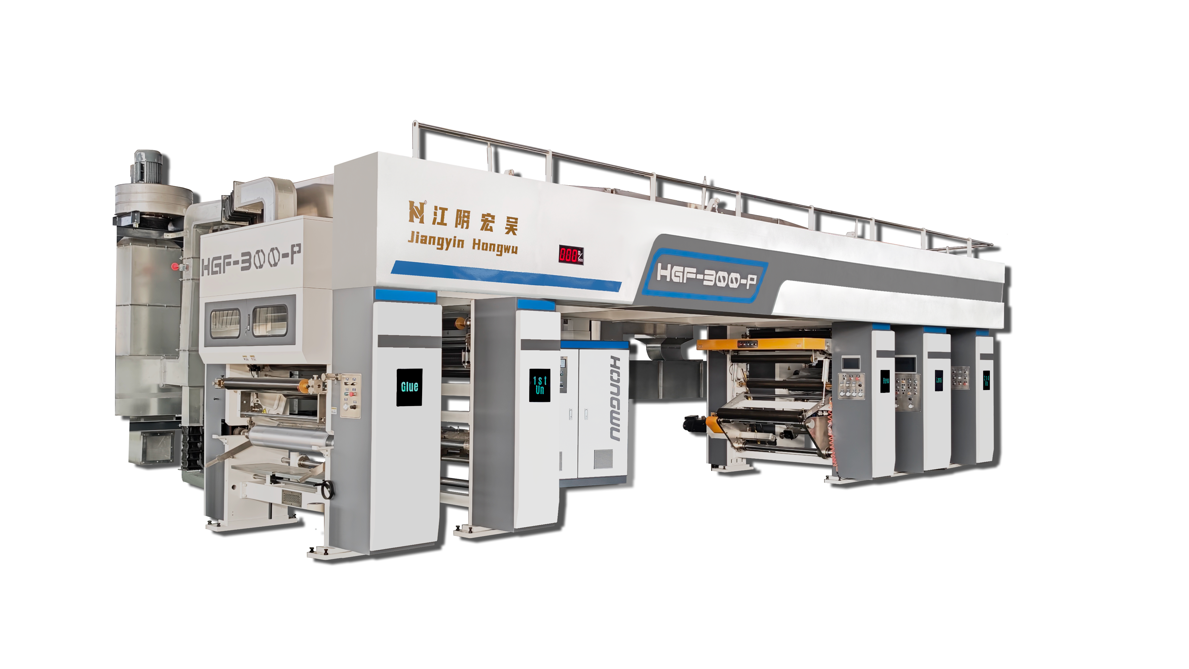
Hongwu dry laminating equipment overview
Material → Coating → Drying → LaminationExplore dry laminators ↗
01 Thermal balance02 Web stability03 Quality verification
01 / Drying & energy management

Three drying zones.
A cascade of reused heat.

The web passes through three progressively hotter zones. Dedicated ducting routes hot air back from Zone 3 to Zone 2, then from Zone 2 to Zone 1.

THREE-ZONE OVEN / CASCADE HOT-AIR REUSE
Three-zone oven with hot-air reuse from Zone 3 to Zone 2 to Zone 1 The coated web travels left to right through Zone 1, Zone 2 and Zone 3. Zone temperatures increase in that direction: T1 is lower than T2, and T2 is lower than T3. Dedicated ducts shown above the oven return hot air from Zone 3 to Zone 2, then from Zone 2 to Zone 1. These are inter-zone reuse paths, not a single-zone circulation loop. Auxiliary fresh-air, exhaust and internal circulation paths are not shown. DEDICATED INTER-ZONE DUCTS Hot air: Zone 3 → Zone 2 Hot air: Zone 2 → Zone 1 ZONE 1 ZONE 2 ZONE 3 T1 T2 T3 Lower temperature Intermediate temperature Higher temperature COATED WEB TRAVEL: ZONE 1 → ZONE 2 → ZONE 3 Temperature rises along the web: T1 < T2 < T3
WEB TRAVEL1 → 2 → 3
TEMPERATURET1 < T2 < T3
HOT-AIR REUSE3 → 2 → 1

Swipe horizontally to view the full diagram.

The cascade arrangement described here uses dedicated ducts between oven zones. This simplified diagram shows the reuse direction; fresh-air supply, exhaust, fans, heaters and internal circulation are omitted. Confirm the final arrangement and temperature settings for the selected machine and material.
01 / Three temperature zones

The web moves towards higher temperatures.

The oven is typically divided into three zones. Along the web path, the temperature settings rise from Zone 1 to Zone 2 to Zone 3. T1, T2 and T3 show this relationship; they are not fixed operating temperatures.

02 / Dedicated reuse ducts

Hot air travels back to the earlier zone.

Dedicated ducting routes hot air from the hotter third zone into the second zone. Hot air from the second zone is then reused in the first. The reuse direction is Zone 3 → Zone 2 → Zone 1, opposite to web travel.

03 / Reduced exhaust & concentration

Verify the airflow balance separately.

Cascade reuse describes where the hot air goes. Reduced exhaust describes how much air leaves the system. Review exhaust flow, solvent load and concentration together, and compare energy use under defined production conditions.

Design boundary

Solvent-containing drying air needs adequate exhaust and a reviewed monitoring and interlock strategy. Recirculation must stay within the approved process envelope.

What to record

Substrate, coating load, solvent system, line speed, zone temperatures, exhaust flow, vapour concentration, residual solvent and energy per accepted output.

General drying ventilation reference (the cascade layout above is based on our engineering explanation): HSE HSG140, drying and curing ovens, paragraphs 217–220 ↗

02 / Tension & web handling

A stable web needs
a defined feedback loop.

Before discussing PID gains, identify the measured signal, the controlled drive and the disturbances the loop must handle.

Two feedback arrangements

Position feedback or measured tension?

A dancer system regulates position; its mechanics and loading influence web tension. A load-cell system measures web force. Their feedback signals and tuning requirements differ.

PID in context

The correction belongs to a larger system.

The controller can trim a drive reference to correct feedback error. The chosen speed or torque architecture, base reference and available correction range matter as much as the controller label.

Changing operating conditions

Check the transition, not only the steady run.

Compare acceleration, deceleration and different roll diameters. Review sensor scaling, mechanical friction, drive limits and the material response before attributing a fluctuation to one tuning parameter.

CLOSED LOOP / PRINCIPLE SCHEMATIC
Illustrative dancer position feedback control loop Position setpoint and measured dancer position are compared. A PID controller produces a limited correction to a drive reference. The drive affects web handling, and the position sensor returns feedback. The diagram illustrates dancer position control, not direct tension measurement. ± PID correction Drive + web path Dancer position sensor Base drive reference Position setpoint Error Limited trim Feedback variable shown here: dancer position
Illustrative dancer position loop. A load-cell loop uses measured tension instead; installed configurations must be confirmed for the selected model.
INPUT

Material & roll

Substrate thickness, width, roll diameter and the required operating range.

CONTROL

Signal & response

Feedback scaling, correction limits and behaviour through speed changes.

EVIDENCE

A labelled trend

Setpoint, measured feedback and line speed on a common time axis, with test conditions attached.

Principle reference: Carotron, dancer control techniques and PID trimming ↗

03 / Coating & lamination quality

Connect the coating step
to the finished structure.

Appearance, drying and bond evaluation answer different questions. Review them against an agreed material structure and sampling method.

01 / APPLY

Coating consistency

Record the adhesive or coating system, mix condition, substrate and application settings. Compare samples across the web and over time.

02 / DRY

Drying conditions

Connect solvent load and residence time with the oven settings. A temperature display alone does not establish the residual solvent in the product.

03 / BOND

Lamination conditions

Record the material combination, nip conditions and relevant tension settings. Evaluate the finished structure using the agreed procedure.

04 / VERIFY

Sample evaluation

Identify the sample, conditioning or curing time and test method. Assess appearance, bond strength and residual solvent where relevant.

Match these requirements to equipment →
From a technical claim to a useful record

Make the trial
repeatable and reviewable.

These are commissioning discussion guides, not reported customer results. Model-specific performance should be supported by a test record for the relevant conditions.

Questions from the production floor

01 Tension changes during acceleration

Compare the speed ramp with feedback and drive correction. Check whether the dancer reaches its travel limit, the correction saturates, or roll diameter changes the response. Verify the actual measured variable before changing gains.

02 Drying changes after increasing output

Record the new line speed and coating load. Compare residence time, zone conditions, exhaust flow and sample results with the earlier run. Use comparable material and acceptance criteria when evaluating energy consumption.

03 Wrinkles or an uneven roll edge

Start with web alignment, roller condition, material variation and tension by zone. Note when the defect appears and preserve a sample. A single controller adjustment does not identify the root cause.

Bring the production question

Let’s discuss the process
behind your packaging.

Share the material structure, working width, output target and the issue you want to investigate.

Talk to our team